The Top Mitsubishi Galant VR-4 Resource

Join the best E39A 1991-1992 Mitsubishi Galant VR-4 community and document your GVR4 journey. Login to browse without most ads.

Slim Fan wiring

4orced4door

Moderator
Joined
Jul 19, 2002
Messages
9,846
Location
Raleigh, NC
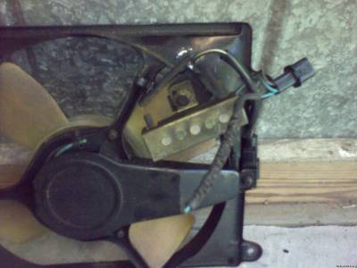
I'm hooking up a slim AC fan, and I want to use the connector from the stock fan so the new fan can be removed easily. The stock connector on the fan has four wires coming out of it, black and blue going to the motor and black and blue going to a sensor or something mounted on the fan. Can I just chop off the wires going to the sensor, and run the black and the blue to the matching wires on my new fan? Will it work normally like this, kick on when it needs to?

I found directions on hooking it up with a switch and a relay, but plug and play like this would be better if it works.


Hertz

Staff member
Joined
Jul 29, 2002
Messages
13,501
Location
Chicago, IL
I think you're seeing the resistor. That can be looped out, I believe. The other two are for the fan.
 

524of1000

Well-known member
Joined
Oct 15, 2008
Messages
574
Location
San Antonio, Tx
I did this to mine (looped the resistor and ran all 4 wires to the 2 that came with the fan) and now they run as long as the battery is connected, or untill I unplug them from a power source /ubbthreads/images/graemlins/dunno.gif
 

alansupra94

Well-known member
Joined
Mar 3, 2010
Messages
1,909
Location
Wayne,NJ
In my car, it looks like the stock fan was removed and the slim A/C fan was shifted....I will double check this.

I might just be putting in 2 slim fans...or just one zirgo. Might just wait for a nice deal on craiglist or ebay to pop up.
 

broxma

Well-known member
Joined
Nov 16, 2009
Messages
911
Location
San Antonio Tx
So I am working this issue to come up with a definitive answer to this question. There are 2 dozen threads about this one single fan, so my goal is to put it to rest. By my best analysis of the schematic, and some help from another member who sent me the schematic, the only difference between the low speed and high speed fan relay, is the resistor in line with the low speed positive output of the low speed trigger wire to the fan. If you remove the resistor, and left everything else the same, the fan would run high speed regardless of which relay triggered it. The relays run in parallel so what appears to happen is with the low speed relay triggered, it gets a resisted voltage through the fan. When the high speed relay triggers, since the low speed has the resistor, the full voltage goes through the non-resisted wire. At most it appears three wires would run to the fan but I am yet to determine if the hot side wires for the fan join before they hit the fan or if the fan has three wires at all. I don't have the stock fan, one of you can chime in here but the point may be mute anyway. It may even have 2 grounds bringing the number up to 4, but the grounds are shared regardless so even if one was missing, it would still work. The only reason to have two grounds would be increased voltage requiring a larger wire.

Steve, looking at the schematic, there is no path from hot to ground through the fan without triggering one of the relays. Even removing the resistor should not spontaneously trigger the fan. Either one of the relays is bad or one of the sensors is bad.

/brox
 
Support Vendors who Support the GVR-4 Community
Boosted Fabrication ECM Tuning ExtremePSI Fuel Injector Clinic Jacks Transmissions JNZ Tuning Kiggly Racing Morrison Fabrications RixRacing RockAuto RTM Racing STM Tuned

Recent Forum Posts

Recent Classifieds Listings

Top